In my previous post, I outlined the basic steps in performing a T56 Magnum (Tremec Magnum 6 speed transmission) swap into your hotrod or classic muscle car. This post will go into detail how I installed a brand new Tremec T56 Magnum transmission into my 1978 Firebird Trans Am.
For a basic outline what is necessary to perform a T56 swap, please see my previous post Installing a brand new T56 Magnum into your hotrod or classic muscle car.
Tremec Magnum vs T56 6 speed transmissions
The T56 transmission is a transmission that was made for specific applications in the 1990’s and 2000’s. IT was then replaced by the TR-6060. The transmission mentioned in this post is actually the “Tremec Magnum 6 speed”. It is similar to the T56, but it is also more similar to the newer TR-6060. It has the same bolt pattern and similar casing and gear ratio options and is made by the same manufacturer of the original T56. In actuality it is a newer and better version than the original t56 from the 1990’s. For the sake of this post post I refer to the transmission at the T56 Magnum, but in actuality the product name is the “Tremec Magnum 6 speed”. You can learn more about the differences in the 6 speed Tremec transmissions on the Tremec website.
Preparing 2nd Gen Trans Am for a T56 Magnum
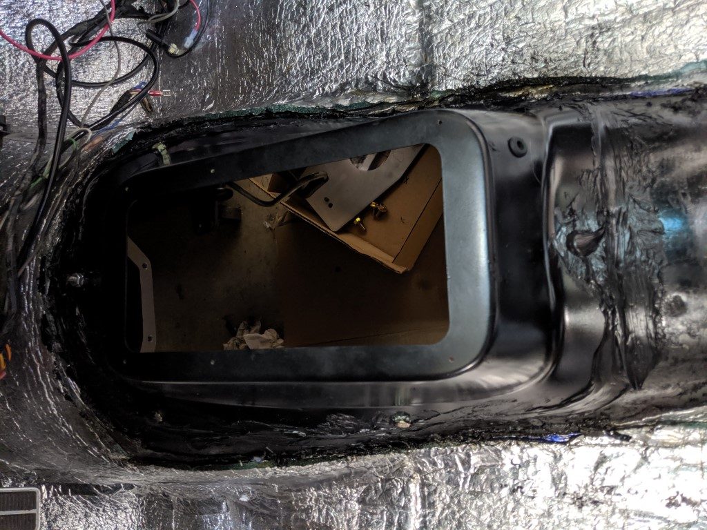
The first second step is to cut a hole in your floor! I hope this does not come to a shock but you will need to cut a hole in your floor to accommodate a T56 transmission. By the way the first step is take lots of measurements!
Now we got the bad news out of the way, I am happy to report that Hooker has created a shifter hump for the 2nd Gen Firebird/Camaro with a T56 Magnum transmission paired to their Hooker LS engine mounts. This is perfect if your car will have an LS engine in it using Hooker engine mounts designed for the hump.
If you are doing a T56 Magnum swap with a Chevy or Pontiac V8, I am pleased to report you can also use the Hooker shifter hump with minimal fineness. It may require some modification to provide clearance at the forward shifter mounting plate (forward most shifter location on the T56 Magnum).
This is not to be confused with a factory F-body T56 transmission. Note the 1998-2002 Factory Magnum locates the shifter further back than the aftermarket T56 Magnum. If you are using a factory T56 the Hooker shifter hump will not work for your application.
Many hotrodders have reported that an F-body 1998-2002 T56 can swap into a 2nd gen with minimal floor modifications, while others have had to make more signification cuts to make a T56 fit. The fitment appears to be attributed to your front subframe and how it is mounted to the rest of the car. If you are using new factory bushings or solid body bushings that use the factory height, you should not have any issues. If you used lowering bushings or your bushings are shot, you will most likely have clearance issues. Either way, the Hooker shifter hump will not work for a 98-02 F body T56 as the shifter is located further back.
Measure Existing Pinion angles and distances
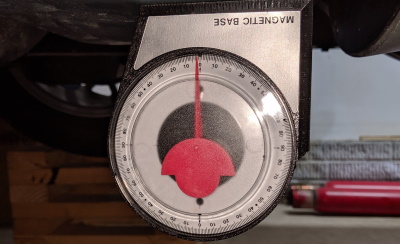
Measure before you remove anything, you will thank me later! First, jack of your car then put the wheels on stands (I used a buddy’s that raise the car 15″ using 2×4 crossed like Lincoln logs) where you plan on working on it during the entire swap and then promptly use an angle finder and take measurements at specific points. Having the car on its wheels, specifically the back wheels allows you to measure angles with the weight of the car on the suspension.
Before you measure pinion angles, you will want to measure distances to use as references to know where to cut. I used the hole for the automatic transmission shifter hole to measure between the block face to the hole. I used this measurement to then factor in where the hole needed to be cut when a 6″ long bell housing plus the T56 Transmission attached will come through. You do not nee dto be precise, you can be off by a good 1/2″ and that will become your buffer area which will work out fine. The shifter hump will want a lot more transmission tunnel removed, do not worry.
Take your angle measurements! I recommend taking some at the oil pan, along the starter (both should be the same if the oil pan is true), drive shaft, and rear axle. I took a few at the rear axle as there is no real good flat surface for the 8.5″ axle. Write all your values down and keep them in a safe place. The plan is to make sure everything is at the same or close to same angles you had before you started.
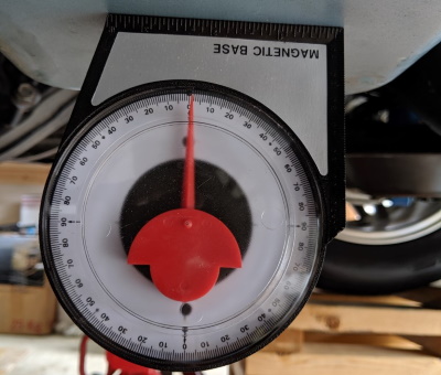
When measuring angles, decide which direction is positive and which is negative. I decided that if the arrow points toward the front of the car that it would be positive angle, and to the back is negative
In my case I had +1 degree at the center of my oil pan, 0 (though hanging toward -1 ) degrees with drive shaft, and +1.5 degree at the rear axle.
Once you have measured your drive shaft angle, you can remove the drive shaft and then measure the rear axle just for your satisfaction. I used the flats where the u-Joint butts up to the pinion shaft coming from the rear axle. AS mentioned earlier I got +1.5 degree at the rear axle.
Now you can put a block of wood behind the engine’s head (between the head and firewall) and then remove your cross member then transmission. The block of wood (I used a 4×4 cut at about 2-3/4″) will hold the engine from tiling further back. Do not worry, the weight of the engine will not damage your firewall, most of the weight is held by your engine mounts.
You should now have measurements and have everything out of your way to start cutting.
Mark for your first cut in the floor with shifter hump as a template
If you are going to use the hooker shifter hump, the first step is to position the hooker shifter hump plate on the transmission tunnel where you think it may go based on previous measurements and reference points. I used the transmission hole position as a center of reference then made my marks a bit more forward than the measurements came to (1/4″ more), and slightly back (1/4″) than your measurements allow. IF your cut is perfect, you will have a 1/4″ gab on all sides. Mark the inside then remove the plate. This is now the safe area where you can cut your first opening.
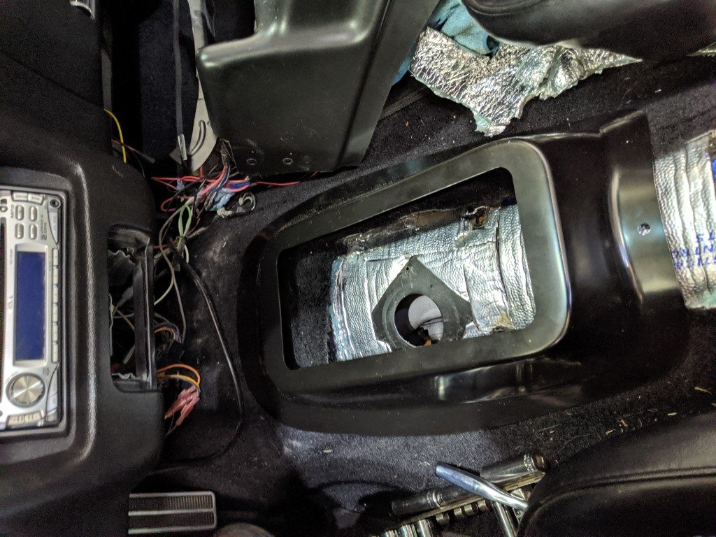
Cutting a hole in the floor
The first cut I made in the floor was following measurements from the block + depth of the bell housing to determine roughly where the transmission would come through the floor. Here are some measurements to keep in mind:
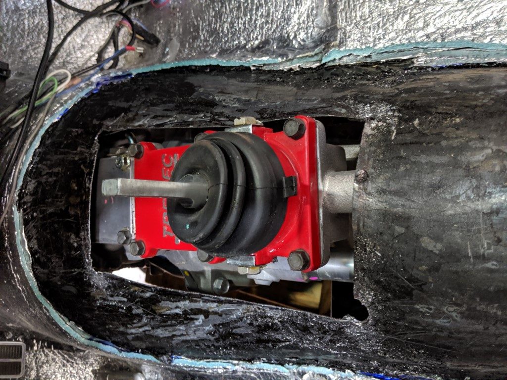
The face of the transmission to the shfiter at the rear most position is 21.125″. You want to add the thickness of the bellhousing you purchased to get the total depth you need for where the shifter position comes out. You also then need to factor in further back clearance for the back portion of the shifter area of the Tremec Magnum. In my case my furthest back cut from the back of the bellhousing was at 30″, or 6+21+3. You can see it just cleared the shifter but I needed to cut back another 1″ for the casting shaft area.
My first cut was crude but did the job. I was cautious not to remove too much as re-adding floor would be a major pain in the rear. As I found later, you really do not have to worry about cutting too much, you will definitely be removing more floor for this shifter hump. When I finally did remove more for the shifter hump I removed a lot more (see photos).
First, drill 4 holes at each corner of your marked cutting area. Then make your first cuts between those holes. My first cuts I did with a sawsall which was very quick (cuts in seconds). The only downfall with a saws-all is it does create rough edges, and it is not as easy to be precise.
I was lucky and could install my transmission without doing more cutting, though thought it allowed me to then focus on where to position the shifter hump. The final markings I made with tape, first around the outside of the shifter hump, then the inside. I then cut along the outside edge of the inside tape.
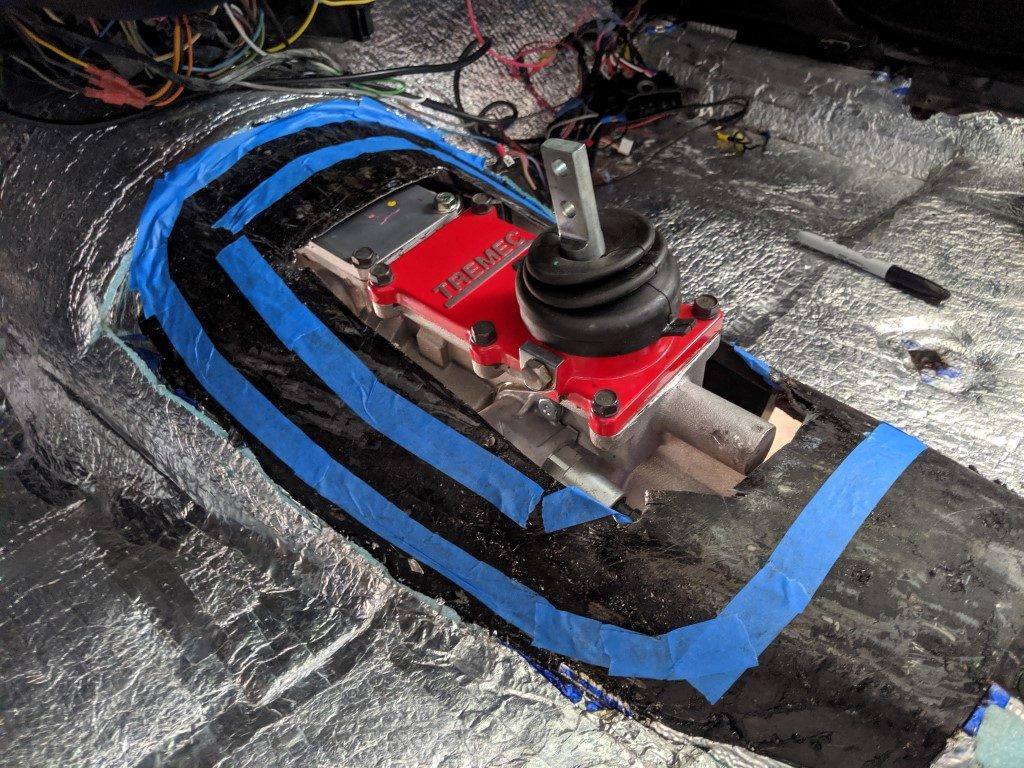
When it came time to cut the final hole, I used an electric body saw. This tool was great once I put a course blade on it, I was able to cut at a reasonable speed and with great precision. It does create a lot of dust but it is worth having the ability to cut right along a line without leaving a jagged edge.
Final installation I used 1/4″ x 20 bolts with lock washers at 4 corners plus a #10-24 thread bolt with lock nut at the top center to help draw the entire hump down tight against the factory floor. I also slightly bent the ears (left and right sides) of the shifter hump to contour better with my transmission tunnel. I then followed up both sides of the shifter hump with Jegs black seam sealer.
More about Hooker’s Shifter Hump
The Hooker shifter hump is intended to work with Hooker LS engine mounts. The LS engine mounts appear to mount an LS engine in approximately the same location as a Factory engine plus 1″, which aligns the back bell housing in the same location for both a Chevy and a Pontiac V8. This is a very important detail. For the Hooker setup, this will put the hump further forward than in the described location for this posting about 1″ to 1-1/2″.
For a Pontiac (and should be the same for a Chevy) V8, the shifter position will be moved back 1.5″. This is due to 2 factors: The engine mount offset of 1″ forward plus the bell housing thickness for a BOP T56 swap is 6″ where-as a factory T56 LS bellhousing is 5.5″.
Note: I may be wrong on the Hooker mounts being +1″, but I believe this is the case as hooker designed it to move the engine forward slightly to also clear the frame for their front engine accessory belt system. Hopefully someone can leave a comment confirming or correcting me on this.
When using this shifter hump with a T56 Magnum with the Hooker system it appears the shifter is forward about 1-2″ and is said to put the shifter right in the same spot as the factory. This makes sense to me as with my setup as you will find out I had to move my center console back 1″ for the factory position in my manual center console to line up.
The Hooker shifter hump, even though it is intended for the LS swap, will work for the Pontiac V8, but it does require some slight modification with a hammer and also changing 2 forward most bolts to button head to give you just a touch 1/8″ of extra clearance. My clearance is now about 3/8″-1/2″ which I am comfortable with.
Parts necessary for installing Hooker shifter hump
- Hooker shifter hump 71223008HKR
- qty 1: M8-1.25 x 25mm Button Head Socket Cap Screw (for forward left cover plate bolt)
- qty 1: M8-1.25 x 30mm Button Head Socket Cap Screw (for forward right cover plate bolt)
- Jegs Seam Sealer Black 300 mL #28046
- Fasteners for top plate and for attaching to floor.
I added 4 nutserts to the top of the hump plate for mounting a plate to the top. I ended up using sheet metal screws and scrap metal from an Ikea metal shelf which was cheaper place to buy steel than at the normal home improvement store.
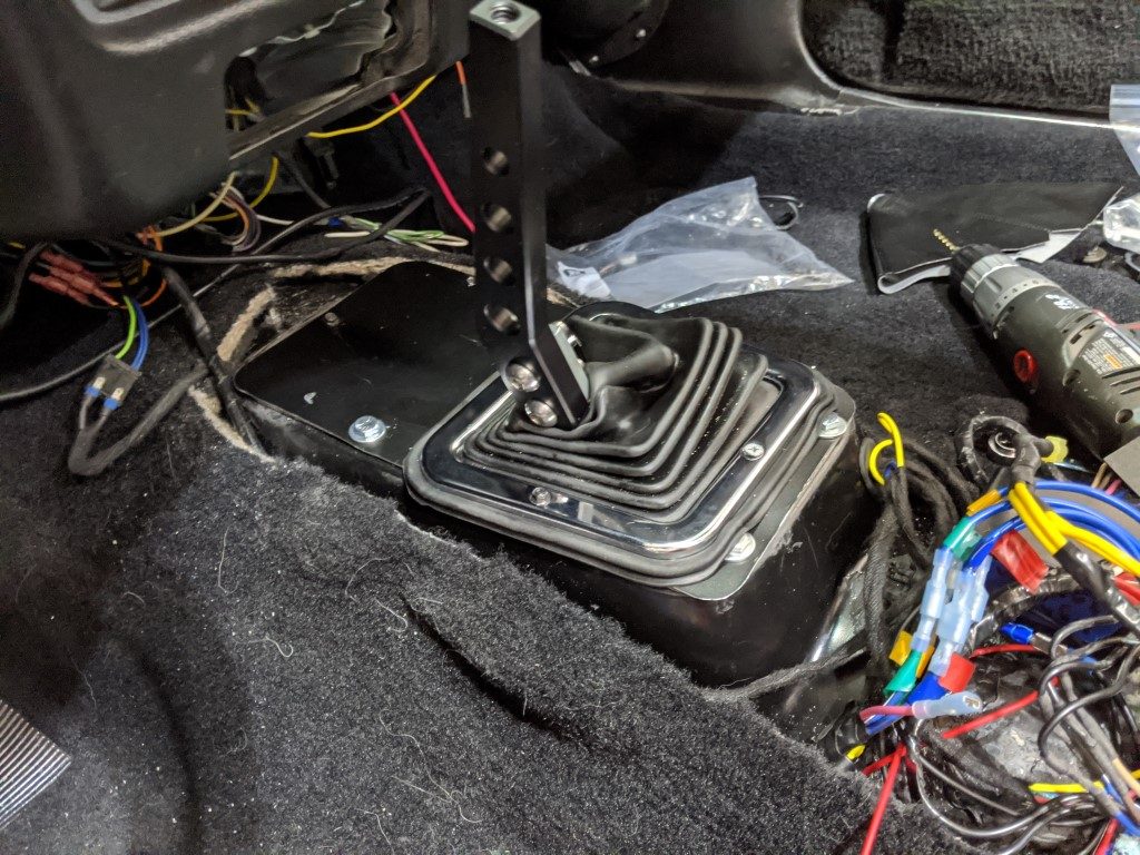
Once the shifter hump was bolted where I wanted it I used seam sealer to seal the seams just as the factory would have done
Indexing your T56 bellhousing
Due to the precision of the T56 transmission and to ensure warranty, the bell housing requires indexing. The transmission shaft should align with the drive shaft bearing/bushing within 0.005″ (five thousands of an inch).
Order the QuickTime Bellhousing Index Plates #RM-130 before proceeding!
There are plenty of websites and resources that explain how to index a bellhousing, I will not go into detail on that. I will share some important tips however.
First, make sure the back face of your engine block is clean and free of any paint. My first indexing I had issues and they stemmed from the fact that the bottom of the one side of the block had paint on it, which was causing the bell housing to point upward. If I did not remove the paint, I would have inadvertently got offset dowel pins to move the bell housing down 7 thousands of an inch, which would have actually caused an issue. Once I had the paint removed and the back of the block clean as a whistle, the indexing of my bell housing was within spec, 0.002″ to the passenger side, 0.003″ toward the top of the engine. This is within the 0.005″.
The only reason I cleaned off the paint from the back of the block was after watching a video on the subject. My first measurement showed I needed offset dowel pins, which lead me to watching videos on the subject, which is when I stumbled upon the video made by QuickTime. They specifically state that the surfaces need to be completely clean (I did that) and free of any paint (what?). Thinking about it, obviously paint would impact the alignment, paint can typically be measured in mils or 0.001″, which is exactly the accuracy we’re measuring. The following video made by QuickTime specifically for their indexing tool was more informative than the instructions that came with the tool.
Just as important, use a torque wrench when bolting on the bellhousing to the block before indexing. If the bolts are not 100% clamping down the bell housing to the block you may end up with a false reading.
Invest in a quality dial bore gauge with mounting accessories as well as purchase or borrow the Quicktime indexing plate RM-130. There is no other tool that works for this, you have to get this one to do the job right.
Throwout bearing adjustment
Throwout bearing adjustment is confusing and different for each product and situation. if you use a McLeod or Tilton throwout bearing, follow their directions to a tee! From what I read both of these throwout bearings have a .75″ total throw and a pressure plate requires about .5″ of travel, which means the throwout bearing when not depressed only has about 1/4″ (.25″) of variance. Most recommend .125 (1/8″) air gap, or a range of 0.1 to 0.15. This provides another 0.1 – 0.15″ for clutch wear. This is very important you get this detail right if you use those throwout bearings.

The factory 98-2002 throwout bearing has a 1″ throw, though I am not 100% sure it uses the entire distance when paired to the factory master cylinder, it is more forgiving than the aftermarket products. Even so, Tick Performance sells spacers of various thicknesses to shim a throwout bearing to achieve an optimal 1/8″ (1/8″ 0.125″ to 3/16″ / 0.1875″ is acceptable) gap. The only challenge is that the factory style throwout bearing uses a spring to constantly apply the throwout bearing lightly against the clutch fingers. This is actually a smart feature as the factory clutch is basically auto-adjusting. You will need to compress this completely to find out the bare minimum distance then subtract from there. The Tick performance spacers come in 3 sizes: .055″, .113″, and .180″. For my application I used one .113″ spacer, which got me at 0.13″ of air gap.
Because of how the factory throwout bearing is engineered with the spring constantly applying light pressure to the fingers combined with a total throw of 1″, I think a factory throwout bearing would work without the spacer for my application. I did lean on the side of caution and added the spacer, which should not harm anything in my situation but I also do not think it was necessary. A 2002 Camaro T56 will not use a spacer and could also have an gar gap of 0.24″ and be just fine.
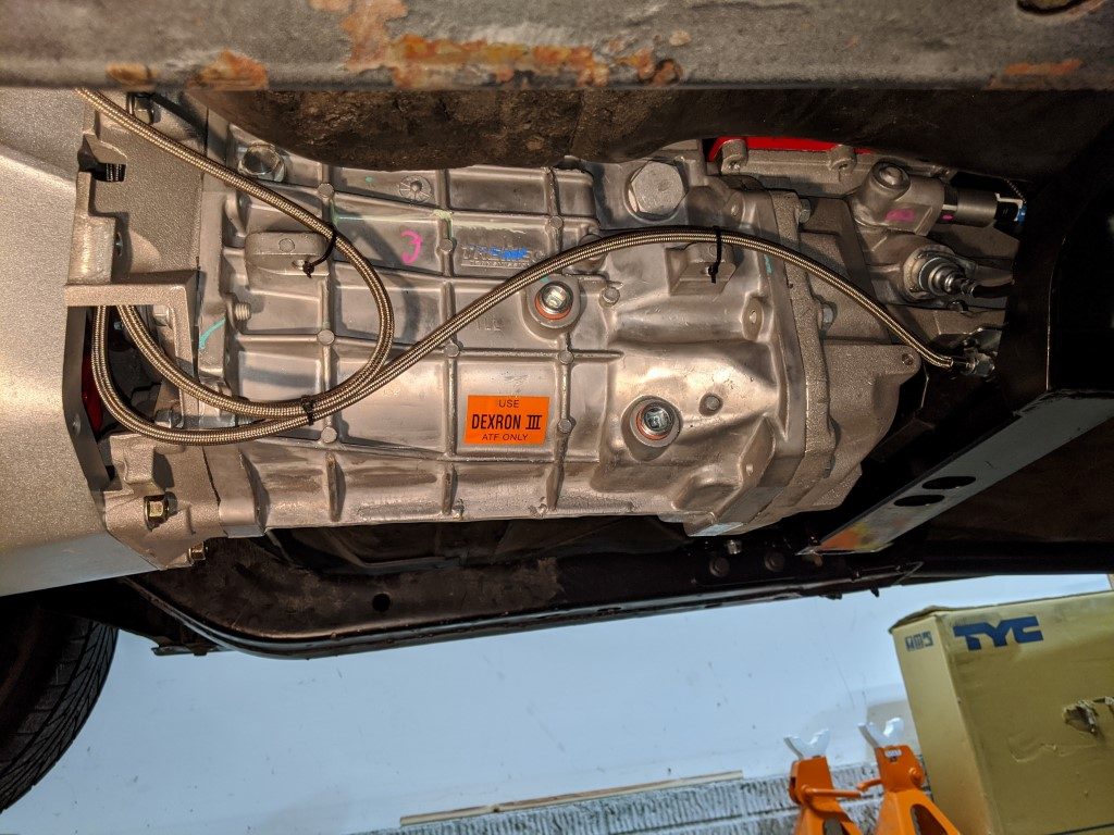
Once adjusted, install the throwout bearing with pressure lines attached to your T56 transmission.
Pilot Bearing or Bushing, what should I use?
I’m not going to tell you which answer is best as it really comes down to your situation. The more important factor is to index your bellhousing otherwise you could mess up your pilot bearing or pilot bushing!
Some facts: The LS engine with a T56 from the factory used pilot bearings.
In the 1960’s-1970’s Pontiac typically used pilot bearings where-as Chevy typically used pilot bushings.
The purpose of the bearing/bushing is to keep the center of the transmission shaft aligned with the center of the engine drive shaft.
From a hobbyist stand point, they both do the job. Tremec recommends the use of a bearing when possible.
If you do research you will find opinions on this, and for most it doesn’t matter but for some, it comes down to what you are comfortable with. A bushing will not fail like a bearing could, rather it will just not perform as it was intended as it wears. A bearing however when it fails, can cause a lot of issues. Typically the issue with a pilot bearing not working is also tied to improperly indexing your bellhousing. Index your bellhousing correctly you will most likely not have issues.
With that said, I opted for a pilot bushing simply for the simplicity of installing. Longevity with a bearing vs bushing is not an issue in my case, I put about 1,000 miles a year on my hot rod, getting 100,000 miles out of it is not a worry in my case. Also If I was installing this on an LS engine, I would go with what GM recommends, which is a pilot bearing.
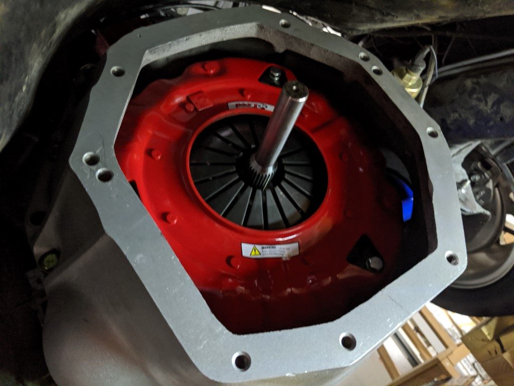
Installing clutch, pressure plate and bellhousing
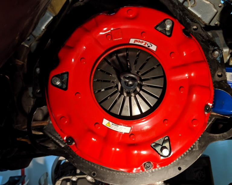
Next step is to install the clutch, pressure plate and bellhousing. This is all rather straight forward, but I do have one tip:
USE A QUALITY CLUTCH CENTERING/ ALIGNING TOOL
Ram Clutches 03-013 Steel Alignment Tool
Read my other post Installing a brand new T56 Magnum into your hotrod or classic muscle car to learn why this tool will save you a lot of time and grief when it comes time to slide your new transmission into position.
When installing the flywheel, clutch pressure plate and bellhousing, make sure you follow the correct torque specifications.
Installing T56 magnum and crossmember
If you have a friend, picking up and installing the T56 Magnum may go easy for you. Otherwise, plan on borrowing or buying a transmission jack which will allow you to tilt and align the transmission as you slowly install the transmission.
Once I had the clutch disc correctly aligned with the RAM alignment tool, I was able to install the T56 in about 5 minutes. I spent more time using the torque wrench and going around the 8 bolts than I did sliding the transmission into place
Which crossmember should I use?
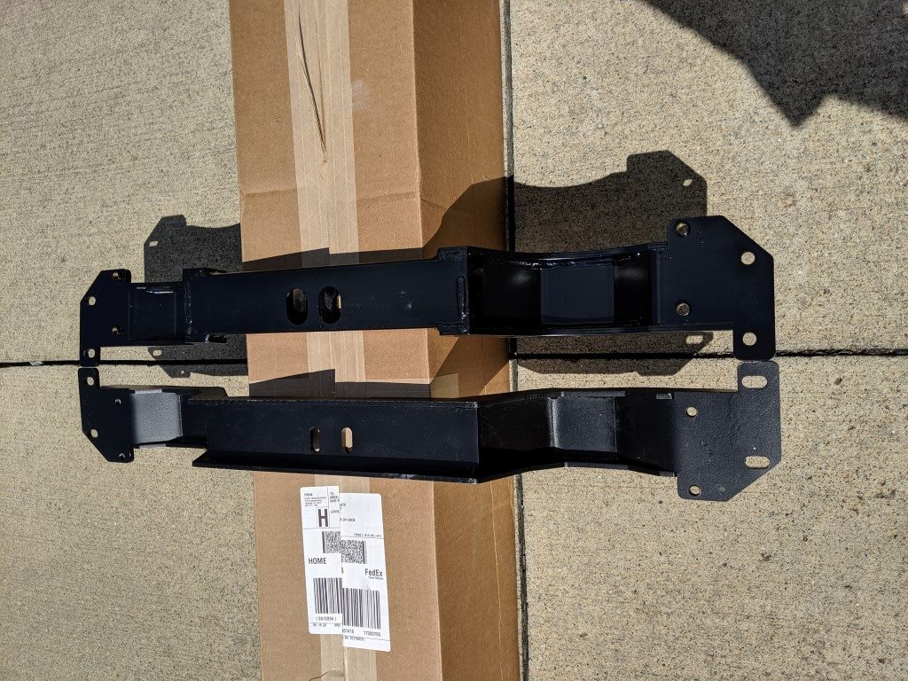
Good question! Because I was using the hooker shifter hump, I decided to go with the hooker cross member HOK-12616HKR. 2 weeks before i started the swap however, I got cold feet. My concern came from reading the fine print that this crossmember only works with the LS engine mounts. I went to the store and purchased the Trans Dapt model above and to my surprise it mounts the transmission in exactly the same way. Angles matched and even the depth it offsets when bolted to the subframe were identical. Obviously they are engineered slightly differently but otherwise they will both put the transmission mount at exactly the same angle and position.
Once the transmission and crossmember is installed, it is time to install the drive shaft. Remember to torque the bolts to spec at the u-joints, over tightening can cause issues here, and under tight can be dangerous.
Measure New Pinion angles
Remember those measurements we took earlier? Now we take them again!
The rear axle we assume did not change. Now we take a measurement of the engine. I now have an angle of +1.5 degrees. This should be sufficient as it matches our rear axle. More importantly, there is no need to put too much thought into this at this point as adjustments are done in 2 degree increments. Since the change is not even 1/2 of a degree, there is nothing much else we can change here.
The drive shaft angle in my situation did not change, it is still about 0 degrees with slightly more movement toward the negative side.
T56 electrical wiring
Electrical can be organized into 3 needs: reverse lights, reverse lockout with a reverse lockout module, and neutral safety switch. In addition, if you are using a modern speedometer the vehicle speed sensor (VSS) can also be used for the speedometer but I am not covering this here as I assume you are installing this keeping your original gauges as did.
Reverse Lights wiring
The reverse light switch wiring is rather simple. It does not matter which is ground or which is not, the 2 wires simply need to connect to the transmission at the appropriate pigtail, the transmission will connect both wires together within the transmission when the reverse lights should come on.
Reverse lockout and reverse lockout module
The T56 transmission comes with a reverse lockout solenoid. This solenoid controls how the gear shift level can or cannot easily go into the reverse gear. You can do 1 of three things: not connect this (not recommended), connect this to the brake light switch (not recommended), or invest in a reverse lockout module (recommended).
STRONGLY RECOMMENDED: T56 Reverse Lock Out Module
Jegs 82513 Reverse Lock Out Module
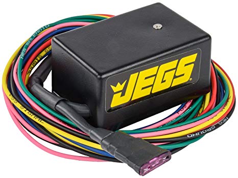
Simply follow the directions included in the reverse lockout module. Wiring is fairly simple, but you will need to provide the appropriate pigtails for your application. I mounted my reverse lockout module underneath thecenter console.
Neutral safety switch
The 1970-1977 Firebird manual transmission cars came with a very simple neutral safety switch which was mounted to the clutch pedal. These parts can be sourced from vendors and is easily bolted on with one 1/4″ body bolt to the metal reinforcement brake pedal assembly.
Firebird / Camaro Neutral Safety Switch
- GM part number: 3983965
- Firebird Central part number: DAS-288
- Ames Performance part number: FM364D
Firebird / Camaro Neutral Safety Switch Pivot Bracket, the harder to find part
- Firebird Central part number: CLU-72
- The Stop Shop (via eBay): TSS263
If your vehicle does not have wires for connecting to this neutral safety switch, you can install your own wiring by using 12 gauge wire to and from this safety switch spliced into the purple wire running to your steering column. The purple wire is the starter wire. When the clutch is not engaged, the starter wire cannot provide power to the starter, its that simple.
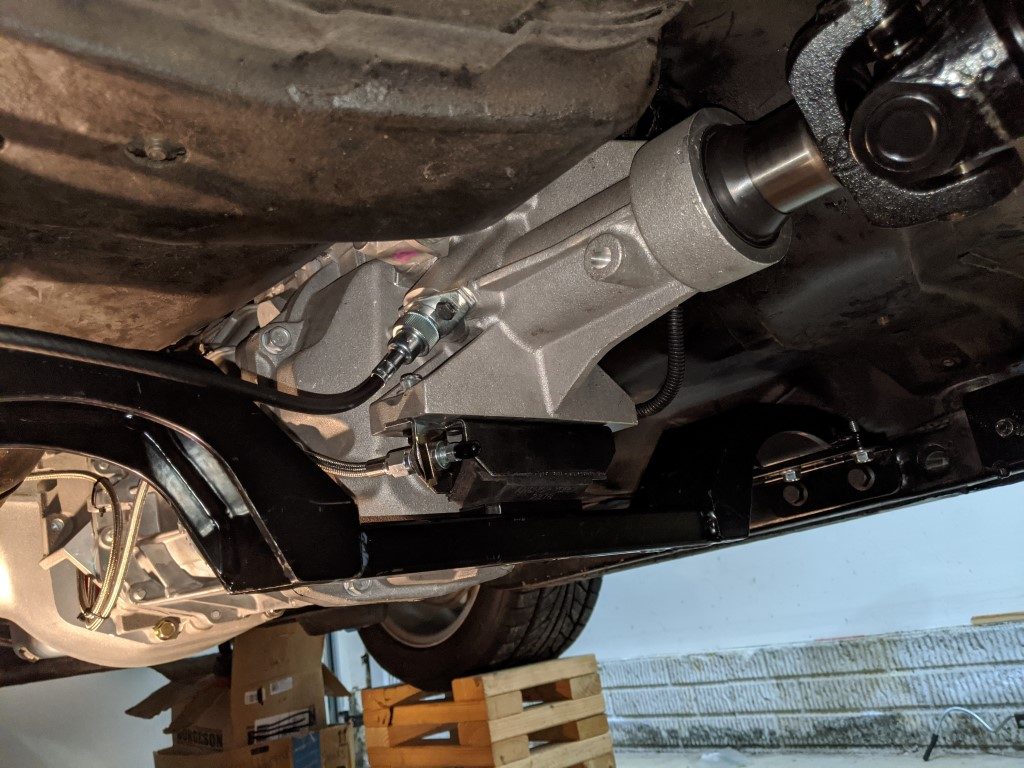
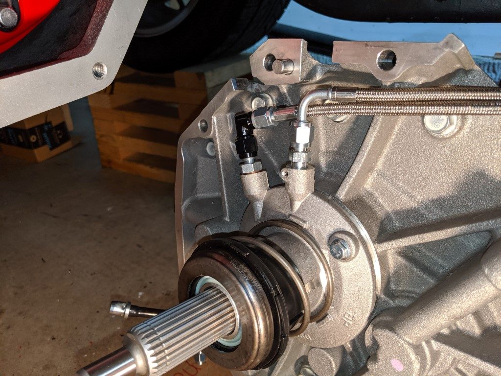
Hydraulic lines
The clutch hydraulic lines can be a bit complicated. In my case I used a factory throwout bearing, but I wanted everything to be 4AN lines. To achieve this ,I had to get adapters and for my bell housing, 4AN lines with 90 degree elbows to clear the bellhousing. changing to 4AN lines allowed me to also use a remote bleeder, which I purchased with a speed bleeder to make bleeding the clutch easier by locating the bleeder screw in a convenient location, by the tailshaft.
Parts I used (you will most likely need different length 4An lines for how you want to setup the clutch):
- Russell RUS-641001 clutch fitting
- Allstar ALL50036-4 to 10mm-1.5 Adapter Fitting
- Russell 641370 speed bleeder -3AN with mounting bracket or Russell 641380 speed bleeder -4AN with mounting bracket (what I used for my application)
- Female 4AN to Male 4 AN Flare 90 Degree Elbow
- Aeroquip FBPA0049-24 24″ long -4AN straight to 90° ends
- Aeroquip FBPA0040-30 30″ long -4AN straight to straight ends
Note: The Russell (Edelbrock) speed bleeder with bracket is hard to find. You can use the 3AN kit they offer and use a 4an male to 3an female reducer adapter to utilize the 641370 3an bleeder with 4an lines. The reduction from 4an to 3an at the bleeder will have no effect on the hydraulics between the master cylinder and throwout bearing.
Tip on bleeding the clutch
When I first started bleeding the clutch I had a hard time getting fluid through the lines. I would press the clutch all the way down and nothing would come out of the bleeder. I had so much air in the system that it could not overcome the checkvalve in the speed bleeder. What ended up working well was to first remove the speed bleeder and allow the clutch lines to simply spit fluid through them to get the bulk of the air out. Once I did this to the point where I started to see a good flow of fluid come out the end of the bleeder line I then put the bleeder screw in. I then cracked it open just a little like I would for bleeding brakes, it then only took a few pumps to get all the air out of the line and I was done.
Fluids!
The last step in any transmission install is to make sure you have transmission fluid in the transmission and brake fluid in your hydraulics. Tremec recommends using Dexron 3 (Dexron III) transmission fluid. I used Dot3/4 brake fluid for the hydraulic clutch. Specifics are linked.
- 4 quarts: Mobil 1 112980 Synthetic Automatic Transmission Fluid
- 1 Quart: Dot 3 or 4 brake fluid
Test with rear wheels off the ground!
Before you take the car on the road, make sure everything works with the car off the ground. I have a detailed list in my write up Installing a brand new T56 Magnum into your hotrod or classic muscle car, please reference that list before taking your car on the road.
T56 Magnum Install in a 2nd Gen Firebird / Camaro done!
Congratulations, you just walked through all of the steps needed to swap in a T56 Magnum into your 2nd Gen Firebird, Trans Am or Camaro! Please feel free to leave comments and feedback below.
Final Parts List
The final list below is all of the parts you will need to swap in a T56 Magnum into a 2nd Gen Firebird/Trans Am with a Pontiac V8. This excludes interior modifications (covered in a future post), shift lever, shift knob, standard wiring supplies, typical bolts/fasteners, and fluids.
When you order a part from the list below, please click the link, it will register my Amazon affiliate which supports the time and money I spend writing and documenting all of this.
- T56 Magnum TUET11009
- Weir BOP to T56 Bell housing (could use a QuickTime RM-8072 BOP instead)
- LUK LSC265B T56 throwout bearing
- Russell RUS-641001 clutch fitting
- Allstar ALL50036-4 to 10mm-1.5 Adapter Fitting
- Russell 641370 speed bleeder -4an with mounting bracket with a 4an to 3an reducer or Russell 641370 speed bleeder -4an with mounting bracket
- Female 4AN to Male 4 AN Flare 90 Degree Elbow
- Aeroquip FBPA0049-24 24″ long -4AN straight to 90° ends
- Aeroquip FBPA0040-30 30″ long -4AN straight to straight ends
- clutch master cylinder (I got the McLeod kit 1434005QD but ended up only needing the master cylinder. If you use the Detroit Speed bracket like I did only get the McLeod master cylinder 139301 or a factory Luk
LMC362) - Detroit Speed 070430 clutch mounting bracket
- MeLeod 75121 clutch and pressure plate
- PRW flywheel 1645570
- Took flywheel, clutch and pressure plate to machine shop to get balanced
- JEGS 82513 Reverse Lock-Out Module + Various pig-tails
Factory manual center console with modified center bezel and Lokar extended shift boot, 8″ shift lever - SMP S712 reverse lights pigtail
- SMP S699 VSS pigtail
- ACDelco PT13212 reverse lockout pigtail
- DORMAN 690023 pilot bushing
- Hooker 12616HKR cross member
- Anchor 2628 or DEA A2628 Transmission Mount
- Hooker 71223008HKR shift hump for LS swap (worked with a little modification)
- Spicer 2-3-6041X yoke
- Modified TH350 cut to length drive shaft with Spicer 2-3-6041X yoke balanced from DrivelineOne in Columbus, Ohio
- Pioneer CA3008 or ATP Y-808 20″ speedometer extension cable
- Classic Instruments SN17 FORD speedometer to GM adapter (you will need to bend the tab flat)
- Speedometer Gear Retaining C1DZ-17292-A
- Speedometer driven gear (pick based your rear ratio and tire size):
- Burgundy: 16 Teeth Gear (Ford Part #C0DD-17271-A)
- White: 17 Teeth Gear (Ford Part #C3DZ-17271-C)
- Yellow: 18 Teeth Gear (Ford Part #C0DD-17271-B)
- Pink: 19 Teeth Gear (Ford Part #C0DZ-17271-B)
- Black: 20 Teeth Gear (Ford Part #C1DZ-17271-A)
If you search eBay you can find a set of 5 or 6 of the driven gears above if you want to have all possibilities on hand.
Thank you!
Thank you Nick from Tremec for his detailed support on questions I had for the Tremec Transmission.
Thank you Don Johnston from DCI Motorsports for your help and advice with various parts of the transmission swap.
Thanks Joel for all the help and for loaning me your transmission jack, it made slipping the T56 a breeze, well once I got the pressure plate lined up right that is!
Related posts:
Installing a brand new T56 Magnum into your hotrod or classic muscle car
Adding hydraulic clutch to 2nd Gen Firebird Trans Am / Camaro