Categories
Engine and Components News Project Trans Am

Modified Factory Pontiac Quadrajet Intake for Square-bore FiTech Throttle Body EFI

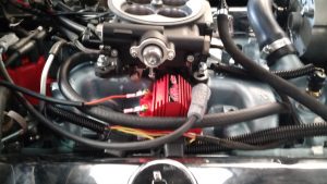
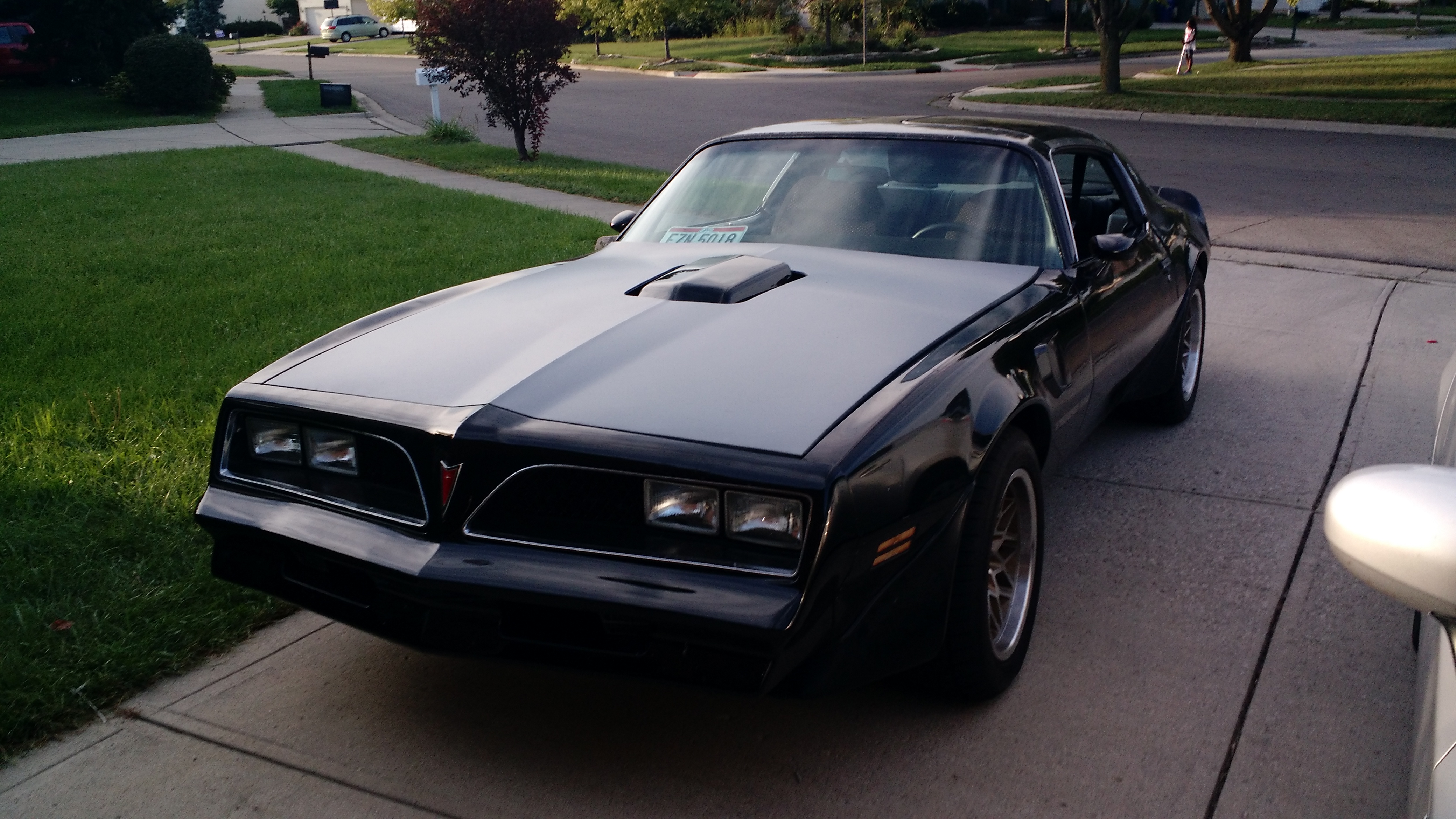
I finally got around to modifying my factory 1972 Pontiac Quadrajet spread-bore intake to accept the square-bore FiTech throttle body EFI. The results are in, the car runs smoother than ever and I can now mount my shaker to the throttle body using the factory air cleaner base!

Modifying a Pontiac Quadrajet intake to accept a square bore throttle body

Note that these instructions are for modifying a Pontiac intake designed for a Quadrajet spread-bore carburetor. Modifying a spread-bore intake for other manufacturers will more than likely be slightly different. Please note that your intake’s runners may be positioned differently thus requiring different attention where to modify.

Modifying a factory intake is not hard and only requires a few tools. Here’s the short list of tools necessary:

  • Reciprocating saw (Sawzall) with bi-metal blades
  • WD40 (or better cutting specific oil)
  • Die grinder (powered by an air compressor recommended)
  • Carbide Burr set (you may want to use both a cylindrical shape one as well as a small ball or tree shaped one to finish off corners)

First, do not modify the intake on your vehicle! First think you need to do is remove the intake manifold. For a pontiac, this requires draining (or partially draining) the coolant enough that removing the intake does not cause drainage from the water crossover in the front of the intake. The draw-down bolt will also require you to remove at least the alternator and in my case, power steering brackets in order to access. I spent more time taking the intake manifold off and bagging/tagging everything than I did actually modifying the intake.

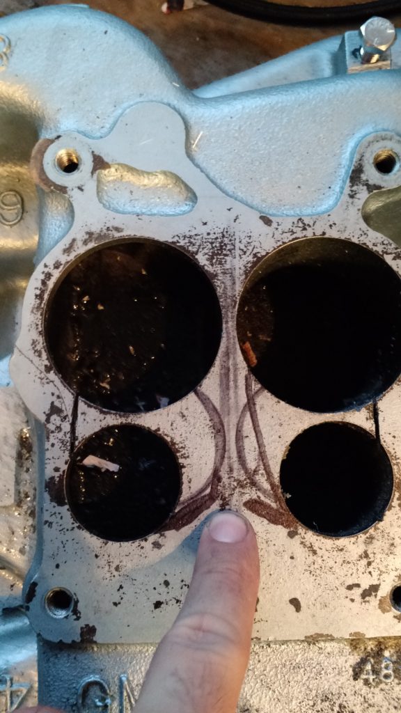
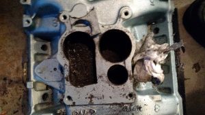
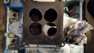
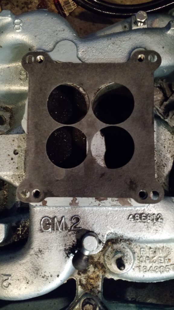
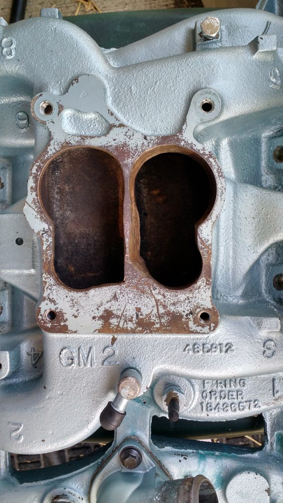
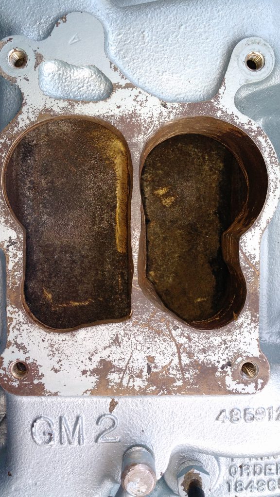
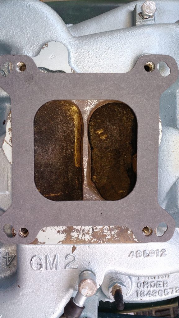
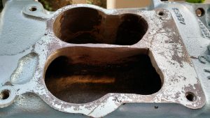
Modifying the intake spread bore openings

You want to make cuts with the saw to remove as much material as possible taking into consideration that some locations you do not want to remove too much material and expose the other side of the intake. Remember these intakes are dual plane and the last thing you want is to poke a hole in the wrong location!

First cuts ran along the outsides. Thes cuts clear the outer most portions of a square bore gasket.
First cuts ran along the outsides. These cuts clear the outer most portions of a square bore gasket.
The 3rd cut took place on the left side (right side if viewing from the drivers seat). This one pretty much opened the one side almost perfectly, requiring only some grinding to the secondary to clear the square bore gasket.
Here you can see using a square bore 4 hole gasket that only a small section of the secondary (top right of the left secondary and top left of the right secondary) needs to be ground down for clearance. The rest of the secondary openings are fine as-is.
The right side of the intake manifold required extra cutting through thicker material. The second cut ran between the secondary to the primary. You may skip this cut if you have a steady hand when using your Sawzall.
The remaining 2 cuts I did at thhe same time. Forming a V, I cut the remaining section between the primary and secondary as close as I could along the centerline of the intake. I was careful not to remove too much material as the walls to the intake runners from the other plane are very close in this area.
With the die grinder carbide burrs I removed just enough material from thetop inner corners of the secondaries as well as smoothed out the areas along the center separating the planes of the intake.
Once I was done I test fit the square bore single opening gasket to the intake. This is the gasket I will ultimately use with the FiTech throttle body.
I will not claim to be a porting expert. I got the job done and all of the rough edges removed, I did not spend the time to remove scratches that I may have left along the walls. You could see them but feeling with your fingernail they were essentially not existent.

Reinstall intake

Once I was done, I washed the intake 3 times then followed the normal directions for installing the intake. The only thing I do that is sometimes not mentioned in manuals is use RTV sealer round the draw down rubber washer (this is the rubber washer that a new intake manifold gasket set will come with that goes between the intake and the timing chain/water pump cover) as well as around the water crossover ports that run to the heads. I am not a big fan of over using RTV sealer, I essentially used enough that when you torque the bolts down you just see a sliver of RTV squeeze out of the mating parts. If you see gobs of RTV sealer oozing out between your parts, then I think you’re using too much.

When I set the intake in place, I just tightened the 10 bolts until they started to grab the intake. Then I torqued the draw down bolt to 15 ft/lbs. Following that I torqued the intake bolts from the center out to 15 ft/lbs, then 30 ft/lbs, then ending with 40 ft/lbs. Everything else I re-connected including the top radiator hose, fuel lines, and wiring for the FiTech.

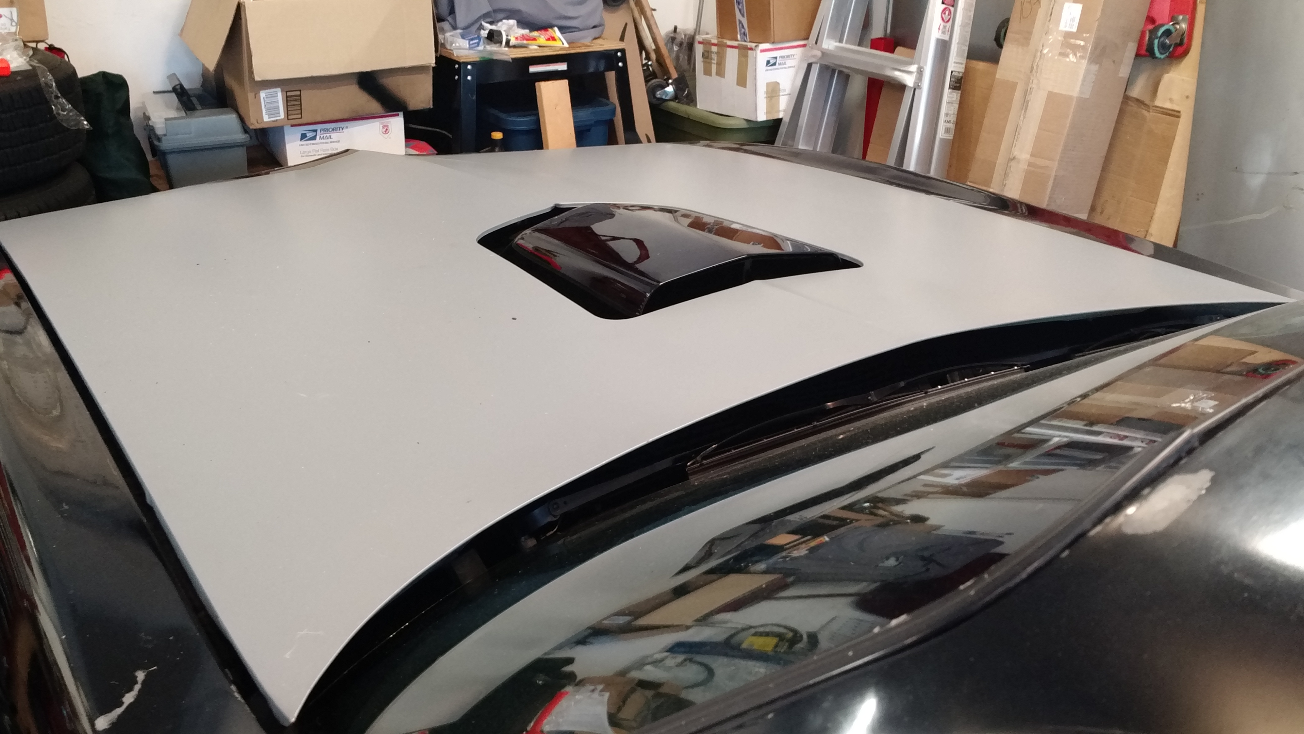
Modified Intake Results: Shaker fits perfectly!

I can now use the factory air cleaner and shaker with the FiTech!

Shaker with factory intake and FiTech throttle bodyShaker with factory intake and FiTech throttle body

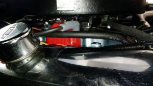
Remounting the Blaster SS Coil

During the process of pulling the intake manifold off the car and modifying it, I noticed that one of the 3 mounts for the Blaster SS Coil had ripped leaving the coil dangling in a not so desired way off of the firewall. Even tough MSD claims you can mount the Blaster SS Coil in any way you like, I determined that the rubber mounts that the Blaster SS comes with are not up to the task of holding the weight of the coil in any other direction but vertically.

At the last minute I created a new mount out of 3/16″ thick 2″ wide aluminum plate and fastened it to the choke side of the intake manifold. I am not sure I will leave it here since I think this creates too much heat in this location, but I will give it a try for a couple weeks at least.

MSD Blaster SS mounted on choke side of throttle body
MSD Blaster SS mounted on choke side of throttle body (I am aware that the throttle body does not have a choke)
The Blaster SS coil clears the air cleaner by over 1/2". This is plenty of clearance for me. My only concern is the possibility of heat build-up in this location, but it may be a good location since it is in the path of the radiator fan.
The Blaster SS coil clears the air cleaner by over 1/2″. This is plenty of clearance for me. My only concern is the possibility of heat build-up in this location, but it may be a good location since it is in the path of the radiator fan.

Comments are closed.